This is going to be another saga of me versus the stupid bureaucratic nonsense generated by large companies that are incompetent at managing themselves.
You get a bad feeling about something, you then find some similar reported issues from the tinternet and then think “oh shit, why did I sign up to this bunch of t*&ts”.
Am I the only one that gets this all the time ? I don’t go looking for trouble but some shite in the sky has it in for me.
My internet provider (John Lewis Broadband) decided to pack up the business and said they would not renew my contract, so a looked around for a good deal for broadband and land phone. I ended up choosing a Vodafone / City fibre with fast fibre and an inclusive call plan. Up to now I had an old fashioned copper line connection with slow ADSL and an old fashioned phone. I decided that I could put up with the vagaries of a VOIP phone service and went ahead and signed up.
On the switchover date, the City fibre boys came around and connected me up to fibre internet in the morning and everything was working after they left.
Except,
For the phone. The router they provided has a socket to connect the phone. I plugged it in. I got a dial tone. I dialled my mobile phone and it worked. Brilliant.
I dialled my home phone number from my mobile and got a message like “number is not recognised, please dial again”.
So these idiots at Vodafone have not registered my old phone number in a database somewhere. They had 2 weeks before the switchover date to get this prepared. They never tested this at switchover and never told me there was a problem. What the f$%k is wrong with you Vodafone ?? They must have to do this countless times with other customers, and how many years have they had to refine and improve their process so that it is razor sharp and 500% efficient ?
So, now how do I tell the relevant t$%t that you’ve f$%ked up ?? Phone them up ?? Phone up a phone company, ha ha very funny ! Go to their website and speak to their automated assistant ?? Not bloody likely, even chatGPT can tell better jokes.
No, I filled in a form and registered a complaint immediately.
Subject landline number not switched over
Brief summary of your experience/query I changed to vodafone broadband package with voip phone. My landline number 0131xxxxxxx has not been transferred across from the old provider (john lewis broadband) and i am unable to receive calls anymore.
Next, a nice man from India phoned my mobile to tell me he was personally looking after my case. Not heard from him anymore after I explained my predicament.
I started to get a sinking feeling that I was re-entering the Kafka black hole called “customer service” so I immediately registered my complaint with the Ofcom ombudsman. But oh no, they only oversee complaints and leave the dirty work to another organisation CISAS.
I looked at the CISAS web site – they need a deadlock/ ADR letter from Vodafone and 8 weeks need to elapse. OK, so I have requested a deadlock letter from Vodafone on their pretty complaints portal. Two full days have elapsed since the switchover. Yes, this is a deadlock situation and wait 8 weeks ?? You’ve got to be kidding.
When the time comes for the Ombudsman adjudication which will be in my favour Vodafone, I am going to push for a decent amount of compensation not the paltry £30 received over the smart meter episode.
I wonder if there is a Ofbum where you can complain about Ombudsman organisations that try to prevent you from complaining ?
I had my old electric and gas meters replaced with a smart meter on 1st February this year.
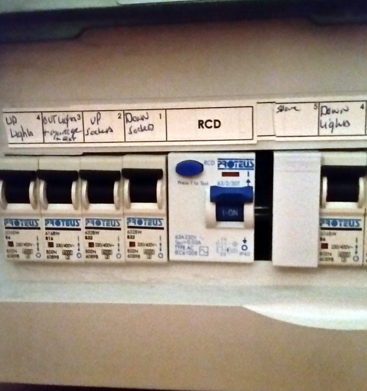
A couple of days later I thought there was a power cut during the night, but I discovered that the RCD circuit breaker on my fusebox had tripped.
This happened again on the next night….
I then proceeded to discover which device was tripping it overnight. It was probably the outside security lights as they are exposed to water.
I isolated these and the RCD tripped again. I isolated every circuit and it tripped again.
I was thinking that there is a coincidence and it was obviously the new smart meter causing the problem. I had to rule out all other possibilities before complaining.
I wondered if there was a rat under the floorboards waking up at midnight to chew through the electric cables. I have a cctv security system and the log for it showed when the mains power failed. It was at 4:30 am give or take a few minutes on two consecutive nights. Rats don’t have alarm clocks !!
It was obvious. The utility company communicate with the radio modem on the smart meter early in the morning to retrieve stored consumption readings for the gas and electric.
The radio transmitter on the smart meter is powerful enough to cause the RCD to trip. I found a few references to this problem on ‘tinternet and also how the companies try their best to avoid liability for the problem.
My freezer is on the same circuit, so if I go away for a few days the contents will be wasted. I bet the electricity company does not want to be liable for this !!
So to prove a point and stop going mad, I built a cover for the smart meter, covered it with aluminium foil and earthed it to the earth bonding point.(you can see the white wire sellotaped to the foil in the above picture) The bottom part was left open to allow some radio waves in and out and to stop it over-heating.
Note that the RCD is 25 cm above the smart meter.
I have experienced no problems for 50 consecutive days. Yesterday, I removed the cover and lo and behold the RCD tripped early this morning.
During this time I contacted the installer (SMS Meter Assets Ltd.) about the problem. I had zero response.
I contacted my electricity supplier (Octopus) about the problem. They acknowledged my email and said this on 2nd March 2022 …..
Hi Peter,
This is an email to let you know I have requested for your meter to be investigated by an engineer.
Our meter operators will be in touch with you in the next few weeks to arrange an appointment.
Thank you for your patience and understanding.
Kind regards,
L
Lfrom Octopus Energy
I am still waiting …….
But not for long, as a complaint will be going to Ofgem soon.
I complained to the Ombudsman after all this baloney and result !!
Octopus sent an engineer to take the radio unit away and it immediately solved the interference problem.
The Ombudsman also got Octopus to pay me £30 compensation for inconvenience caused.
I now have a dumb smart meter (DSM) and have to send meter readings by hand again. So that was a total waste of effort by all involved.
This post is an extension to a previous post about tempo mapping. There is a feature “Create measure from time selection” that you can use when you right click a time selection of some MIDI data. This feature allows you to specify the time signature and number of bars between two markers. For instance if you have two hit points on a piece of video that have markers and you want the bar measures to start from marker A and finish at marker B. You double click on the time base, select the function from the pop up menu, enter the time signature and number of bars and hey presto the bar and beat grid is aligned to what you want.
The number of bars you choose obviously determines the tempo, the more bars you pick, the faster the tempo is because you have a fixed time interval. In my example the time between A and B is 10.690 seconds
Suppose you select 8 bars of 4/4 . In my example the tempo is set to 179.607 BPM. If I select 9 bars of 4/4 the tempo is set to 202.058 BPM. Suppose that the tempo I want is somewhere between these limits. Well, intuitively you would enter a fractional number of bars at 4/4 e.g. 8.5 . Reaper cannot do it, although film composers do this all the time. If I could enter 8.5 bars I could get a tempo of 190.833. This would mean 8 bars of 4/4 followed by one bar of 2/4 .
I have come up with a simple-ish work around. This is to initially work with just beats and not bars. We first need to compute the number of beats to fit in between the markers A and B in order to get the desired tempo. So we use a time signature of 1/4 and a number of beats required instead of the number of “bars” when entering data into the “Create measures ..” dialog.
In my example I enter 34 beats which is 8 bars of 4/4 and 1 bar of 2/4. (you could have other more complex combinations). When you enter the number of beats on the dialog it shows the calculated tempo, so you can easily find the nearest desired tempo. In my case I wanted a tempo of 190 BPM.
When you confirm the dialog, you have 34 bars each with one beat and a suitable tempo of 190.833 BPM.
You must then work out how many bars at 4/4 there are and the number of remainder beats. In my case I have 8 bars of 4/4 and 2 remainder beats. (8 x 4 + 2 = 34 )
I then put a marker at the end of the 8 bars of 4/4. Lets call it marker C. I then use the “Create measures ..” dialog again for the region A -> C and enter a time signature of 4/4 and 8 bars. The tempo should remain the same. I use the dialog again for the region C -> B and enter a time signature of 2/4 and 1 bar. The tempo should remain the same.[
[A] 8 bars of 4/4 [C] 1 bar of 2/4 [B]
Its a bit tricky, but the essential initial task is to get an integral number of beats between your markers A and B.
Vocaloid 5 is one of several voice synthesizers that allow you to create vocal lines from entered notes and lyrics. I purchased this product to allow me to mock up songs and add harmonies to existing songs. The synthesis is quite good but still has that robotic/Melodyne quality. It is quite difficult to produce a lead vocal line and get the intended phrasing right, however it is acceptible for my modest needs. There is a large scope for altering the expression and quality of the voice.
There are several products out there, many are Japanese and difficult to evaluate.
I tried “Emvoice” which requires an Internet connection to a voice server. The vocal quality was good and on the “pure” side. There is only a man and woman voice. Where is the chipmunk ? The other products had access to different voice banks. There was no additional control over expression and inflexions. For example, to add vibrato you have to chop the note up manually and adjust the pitch of each individual segment. It would not take much software effort to have a function to do this automatically. I also thought the user interface was pretty poor for the price. It was not well integrated with Reaper although it was a VST. I think this product is still undeveloped and may blossom into to something really good. However if they go bust you can say goodbye to your cash and the operation of the software. The demo is limited to 7 semitones for each voice.
I tried “Alter/Ego” which is a free product. The voices were very robotic. The note placement was well-integrated with the Reaper MIDI editor. The lyrics are typed in separately and each syllable is assigned to a note sequentially. Although this is an improvement on Vocaloid and Emvoice, it is difficult to tie the lyrics to the notes directly and easy to get the lyrics out of synch with the notes. I stuck with this product however as it is a nice way to develop a voice line before importing it to VOCALOID.
Vocaloid 5
Vocaloid 5 is released as a stand-alone editor application and some VST components. There is a VST to plug into Reaper, but this really acts as a conduit between the two separate applications. The DAW integration is therefore clumsy and is not ideal for a producer’s workflow. I would have expected better for an expensive product.
The MIDI integration is also very poor, in fact MIDI does not work for the VST version and it is not possible to record MIDI directly from the keyboard. The transport and cursor control requires the “Rewire” VST so that the controls are synchronised between the two applications.
Only one instance of VOCALOID can run, so you cannot add several vocal tracks to Reaper. You must add tracks to the VOCALOID editor application itself. You do not see the notes on the Reaper tracks and you cannot splice tracks and copy/paste as usual with MIDI.
The actual operation of VOCALOID is described in numerous YouTube videos and I will not detail it here.
My workflow described
I have devised a workflow for using VOCALOID.
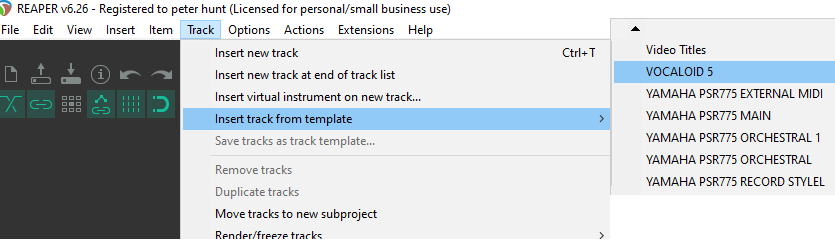
I have created a Track Template as with all my other workflow tasks. This contains some instructions, a track with “Alter/Ego” ready to record MIDI from the keyboard and an empty track containing the VOCALOID VST’s.
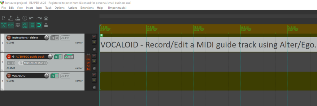
I select the Track Template and the tracks are added to the project…
I have put the instructions on the first dummy track. This can be deleted later.
The second track uses the “Alter/Ego” VST plugin and is ready to record from my MIDI keyboard.
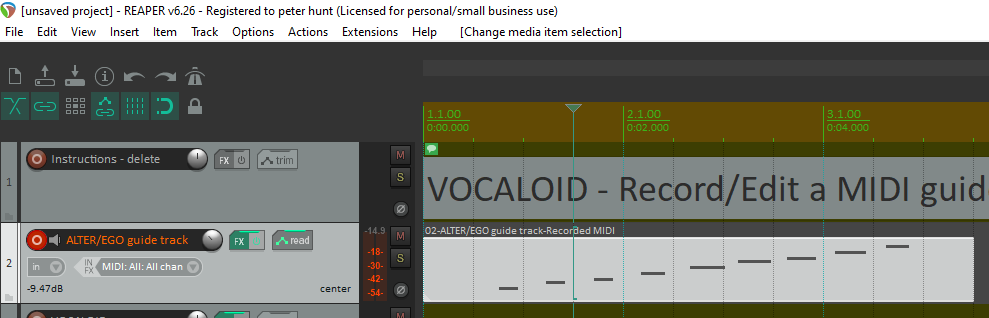
I play around to create a vocal line in the same way as creating any other instrumental line from the keyboard. I hear a vocal sound with the duff lyrics which can be inspiring or totally tedious. The words simply cycle around, one syllable per note if they are detached.
Once the track has been recorded, ita can be edited and reviewed. It is best to try and get the timing right at this stage as any further work takes place in the VOCALOID application.
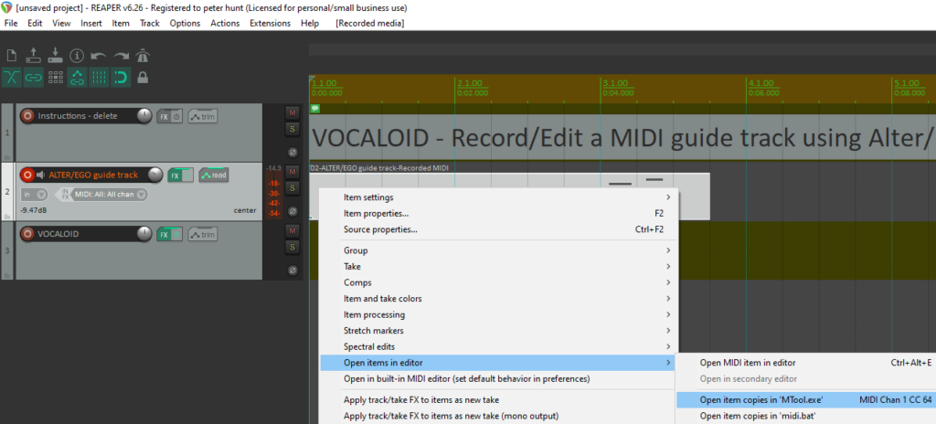
I then select the MIDI item for the vocal and invoke my external MIDI editor. This serves two purposes :
To create a MIDI file for the item
To copy the file location path to the clipboard
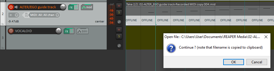
I press cancel and I am ready to transfer the MIDI to VOCALOID. Once I have done the transfer, I delete the “Alter/Ego” track.
Note that the VOCALOID track in Reaper has a second VST “Rewire VOCALOID5”. This is necessary to synchronise the cursor control and transport control between the two applications. When VOCALOID 5 is initially installed, the VST is placed in the folder “C:\Program Files\Common Files\VST2” and this needs to be scanned in the usual way.
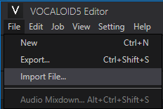
The VOCALOID 5 application is automatically started for the track when the track is added or the project is opened. You have to import the MIDI item using the VOCALOID 5 file menu as shown. I simply paste the file path using CTL V in the file open dialog.
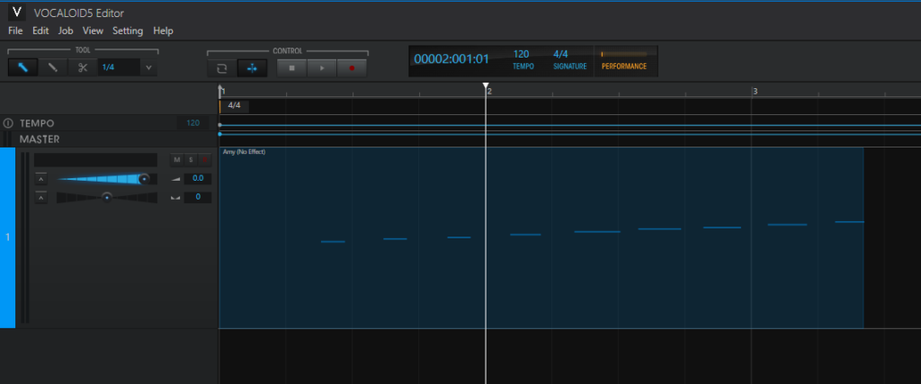
The MIDI track is then added to the editor.
You then double click on the item to open the “MIDI” piano roll editor. The lyrics can then be added in one go or on a per note basis.
I require an expression pedal to add to my Reaper recording setup. The simulated orchestral instruments need this type of control to make them sound realistic. I have a MIDI controller with hand operated sliders, but they are sometimes inconvenient, especially when playing with two hands.
I could buy one off the shelf but that is no fun. I thought this project would be a good learning exercise in using the STM32 Bluepill microcontroller board. This would exercise the following:
Programming the USB connection to a PC.
Developing and testing the MIDI USB interface.
Using the on-board Analog to Digital converter.
The expression pedal needs to convert the angular displacement into a control voltage that can be measured by the ADC on the micro-controller. There are several ways this can be done:
Use a potentiometer (rotary or linear) and use a mechanical linkage to operate it.
Use a hall effect sensor and moveable magnet.
Use a light dependent resistor and a moveable light source. The resistance varies with the light intensity.
Use a combination of infra red LED and photo transistor. Attach a reflector to the pedal and measure reflected IR light.
Use a reverse polarity LED and measure the time for it to discharge. The micro can charge and measure using a single GPIO pin. Use a moveable LED to illuminate it.
The STM32 has a 12 bit ADC on-board which can measure the voltage range 0v to 3.3v as 4096 discrete steps. (It is not always necessary to use an ADC and it is possible to measure voltages using a capacitor or an analog comparator. e.g. on 8 bit PICs)
There are several foot pedals manufactured with an internal variable resistor. These are used for guitarists and sewing machinists. Here is a selection:
Nektar NX-P Universal. cost about £20M-Audio EX-P – Expression Pedal. cost about £13
I could easily use the above pedals and add a USB interface based on the STM32. I could also buy an inexpensive foot switch pedal and modify it to provide an analog output.
I decided to manufacture my own pedal using a light dependent resistor (LDR) and moveable LED as the sensor. Using an optical sensor simplifies the pedal as there is no mechanical linkage and it can adapt quite easily to the amount of travel. The LDR is glued to the base of the pedal unit and the LED is glued to the underside of the pedal.
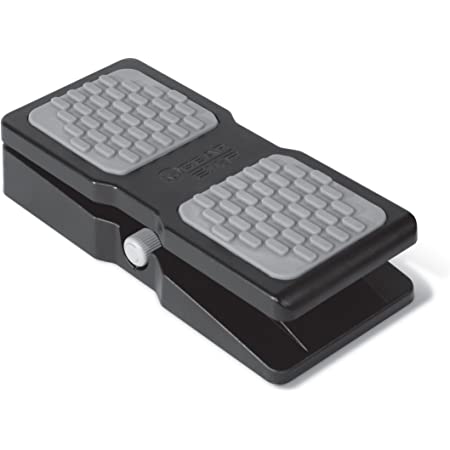
I constructed the pedal using chip board. I used a gate hinge and hacked a spring assembly. I toyed with the idea of using a cheap hole punch which would provide both the hinge and spring return assembly.
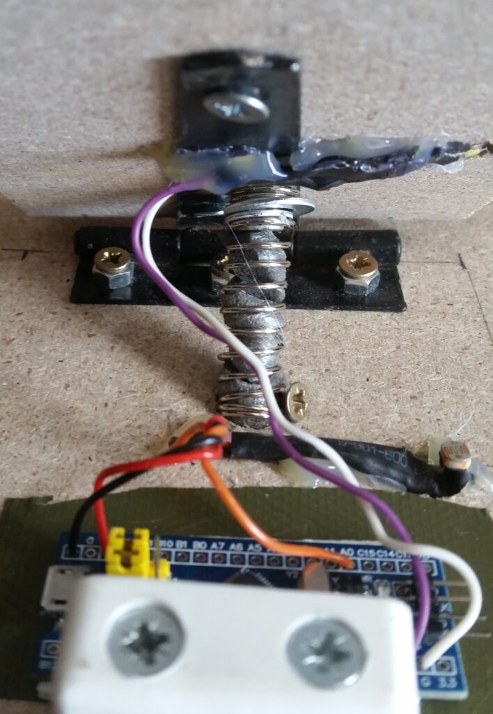
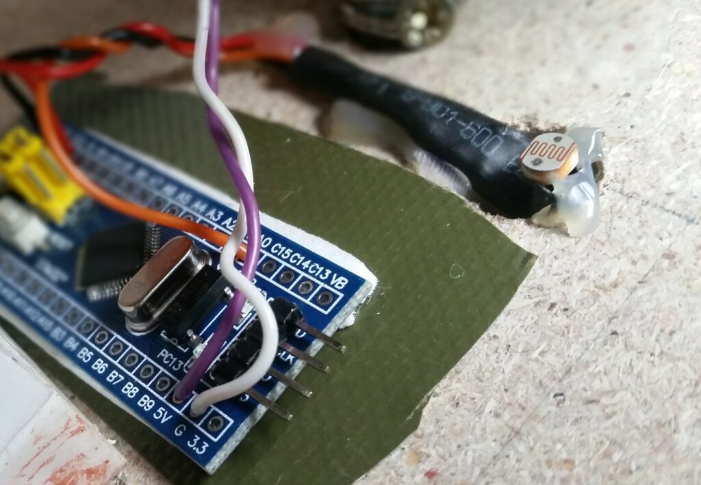
Forward view of pedalBackward view of pedal showing hinge and spring. STM32 micro is stuck down with double sided foam sticky table. Inside of spring is stuffed with foam plastic to act as a damper. The white plastic widgits provide an end stop to prevent crushing of the micro.This shows the LDR glued in position. A resistor forming part of the potentiometer is inside the shrink wrap sleeve.This shows the LED assembly glued to the underside of the pedal. A current limiting resistor is inside the shrink wrap sleeve. The LED is a surface mount device and soldered to the tracks of a small pice of vero board. They are very bright devices for their size !
The STM32 microcontroller is plugged into the PC and is installed as a MIDI device by Windows 10. The pedal is powered by the USB +5v power supply. It can then be accessed as an input on REAPER. MIDI control change messages with ID=1 are sent whenever the pedal is pressed or depressed.
The analog limits are not known when the device is plugged in, so the first few seconds are used to establish the baseline voltage with no depression. The pedal then monitors the analog voltage and establishes the maximum voltage. (The pedal needs to be pressed down fully). The software scales the measured voltage accordingly to produce a MIDI range of 0 .. 127 units.
Circuit diagram
Software
The software is developed using FreePascal and Lazarus. It is compiled on the Windows PC and downloaded to the STM32 using an intermediate Raspberry Pi as described previously. This allows me to debug the software in situ. The compiler toolset and STM32 executive has been developed by Michael Ring. (MBR framework) I have also used a USB library written in Pascal (SimpleUSB) and altered it for my own purposes. I have also used a Pascal library that supplies low level access to the hardware for running the ADC.
I have made use of FreePascal classes and object orientation. It is necessary to supply a heap manager to allocate memory for the dynamic objects. I wrote a very simple memory manager to allocate static memory and that works successfully.
Developing USB classes is a real pain in the butt and difficult to debug with a device driver running on windows. There is a large amount of initial configuration messages required just to get the minimum communications to work. It seems to be totally over-engineered in my humble opinion.
The Windows operating system provide generic USB device drivers for Virtual Comm ports (CDC class), MIDI, Mass storage devices, Human interface (mice,keyboards) and Audio.
I have managed to get the USB MIDI to work reliably in one direction from STM32 to PC. The other direction however is not working properly yet and can totally hang up the Windows devices handling. This is despite using a configuration recommended by the USB consortium. Only one direction is required however for a USB pedal.
ADC control
There are 8 ADC channels available. I am using the first one on pin A0.
There is an initial setup of the ADC which includes self-calibration :-
var
  ADC_InitStructure: TADC_InitTypeDef;
  vADC1: TADCRegisters absolute ADC1_BASE;


procedure initialise_ADC;
  begin

    RCC_APB2PeriphClockCmd(RCC_APB2Periph_ADC1, TState.Enabled);

    ADC_DeInit(vADC1); //Power-on default


    ADC_InitStructure.ADC_Mode := ADC_Mode_Independent;
    //Independent conversion mode (single)
    ADC_InitStructure.ADC_ScanConvMode := TState.DISABLED; //Convert single channel only
    ADC_InitStructure.ADC_ContinuousConvMode := TState.DISABLED; //Convert 1 time
    ADC_InitStructure.ADC_ExternalTrigConv := ADC_ExternalTrigConv_None;
    //No external triggering
    ADC_InitStructure.ADC_DataAlign := ADC_DataAlign_Right; //Right 12-bit data alignment
    ADC_InitStructure.ADC_NbrOfChannel := 1; //single channel conversion
    ADC_Init(vADC1, ADC_InitStructure);

    ADC_TempSensorVrefintCmd(TState.Enabled); //wake up temperature sensor
    ADC_Cmd(vADC1, TState.Enabled); //Enable vADC1
    ADC_ResetCalibration(vADC1); //Enable vADC1 reset calibration register
    while (ADC_GetResetCalibrationStatus(vADC1)) do ;
    //check the end of vADC1 reset calibration register

    ADC_StartCalibration(vADC1); //Start vADC1 calibration
    while (ADC_GetCalibrationStatus(vADC1)) do ; //Check the end of vADC1 calibration

    //Select 1.5 cycles conversion for channel 0
    ADC_RegularChannelConfig(vADC1, ADC_Channel_0, 2, ADC_SampleTime_1Cycles5);

  end;
The following shows a call to read the ADC channel0 into a WORD variable
var
   aval : word;


    ADC_SoftwareStartConvCmd(vADC1, tState.Enabled);
    while (not ADC_GetFlagStatus(vADC1, ADC_FLAG_EOC)) do ;
    //Wait for conversion complete
    aval := ADC_GetConversionValue(vADC1); //Read ADC value
    ADC_ClearFlag(vADC1, ADC_FLAG_EOC); //Clear EOC flag
USB communications
I have created a tMIDI class to handle the USB communications. This class inherits the tEasyUSB class that does all the heavy lifting. The tMIDI class has definitions of all the required USB configuration messages.
unit easyMidi;
{$mode objfpc}{$H+}
interface
uses
  easyUSBconfiguration,USBCore,simpleusb;
 type

  TEasyMIDI = class(TSimpleUSBDevice)

function Device_record : PUsbDeviceDescriptor;override;
function Config_record : pAry;override;
function Strings_record : pStrings;override;

function DoControlReq(AEndpoint: byte;
  var ARequest: TUsbControlRequest): TSimpleUSBResponse;override;

function DoControlRX(AEndpoint: byte;
  var ARequest: TUsbControlRequest): TSimpleUSBResponse;override;

end;
var
   midi: TEasyMidi;

procedure GPIO_USB_PORT_Configure;
begin
  // USB
  GPIO.PinMode[TNativePin.PA11] := TPinMode.AF0;


  GPIO.PinMode[TNativePin.PA12] := TPinMode.AF0;
  GPIO.PinDrive[TNativePin.PA12] := TPinDrive.None;
  GPIO.PinOutputMode[TNativePin.PA12] := TPinOutputMode.PushPull;
  GPIO.PinOutputSpeed[TNativePin.PA12] := TPinOutputSpeed.High;

  // USB Attach
  GPIO.PinMode[TNativePin.PD2] := TPinMode.AF0;
  GPIO.PinDrive[TNativePin.PD2] := TPinDrive.None;
  GPIO.PinOutputMode[TNativePin.PD2] := TPinOutputMode.OpenDrain;
  GPIO.PinOutputSpeed[TNativePin.PD2] := TPinOutputSpeed.High;

  GPIO.PinValue[TNativePin.PD2] := 1;
end;


procedure mainUSBinit;
begin
  GPIO_USB_PORT_Configure;

  midi := TEasyMidi.create;
  with midi do
      begin
        Enable;
        SetConnected(True);
      end;


  GPIO.PinValue[TNativePin.PD2] := 0; // pull-up on D+ line for usb

end;
The above code sets up the pins used for the USB interface.
Pin D23 (PA12) is the USB D+ line, and D24 (PA11) is the USB D- line.
The USB interface is poll driven. The next snippet shows how a MIDI control message is sent to the PC. The MIDI messages are sent as 4 byte packets across the USB link.
var
  txb: array [0..3] of byte;
  midi_val: integer;
  old_midi_val: integer;


while true do
begin
   midi.poll;

{stuff here to measure ADC, calibrate, scale and condition input. etc.etc.}

   if midi_val <> old_midi_val then  //val changed
   begin
        old_midi_val := midi_val;

        // MIDI CC msg
          txb[0] := $0b;
          txb[1] := $b0;
          txb[2] := 1;  // modulation wheel
          txb[3] := midi_val;
          midi.Write(txb, 4);
   end;
end;
In conclusion, the project has been successful and has been my first dip into the world of 32 bit Micro-controllers. The pedal works very well. I have added a slight amount of smoothing to prevent abrupt changes and that suits my control of the instrument expression.
I have yet to add a nice enclosure, some rubber feet and a rubber covering for the pedal itself. The mechanics are a bit imprecise and perhaps I should use a hole punch for the hinge after all.
There are 8 analog channels so it would be easy to add extra pedals to the setup.
I am also going to provide a calibration button to invoke a specific calibration of the idle and fully pressed values and write these to the flash memory. This means that I will not have to do any calibration at start up.
The nice thing with using optical sensors is that they can be easily applied to other existing mechanical configurations without much disruption.
This post is about de-bugging the STM32 Blue Pill card using Lazarus and Free Pascal. A previous post describes how to develop and build programs on a Windows PC. The program can be downloaded to the target board and de-bugged with the minimum of fuss using this method.
A Raspberry PI Zero card is employed to run an OpenOcd server that drives the STM32 debug interface and communicates with the Windows PC. I use the Raspberry PI Zero cards in “headless” mode. This means that they are not connected to a monitor, mouse or keyboard but are simply powered by a 5v supply. They have a WiFi connection to my network. The PI runs “VNC server” to provide a virtual desktop and “ssh” to provide an alternative command line interface. I created a minimal image for the PI which can be copied to a new SD card from the PC whenever I wish to build a PI system. This has the WiFi user and password stored so that they work out of the box.
Basically this installs the C compiler tool chain, fetches the sources for OpenOcd, builds the toolset, installs it and prepares an area to run the debugger.
sudo apt-get install git autoconf libtool make pkg-config libusb-1.0-0 libusb-1.0-0-dev

git clone http://openocd.zylin.com/openocd

 cd openocd

 ./bootstrap

 ./configure --enable-sysfsgpio --enable-bcm2835gpio

 make

 sudo make install

 cd ~

 mkdir bootloader

 cd bootloader
You then have to create a configuration file for the STM32 Blue Pill card by creating a file called “openocd.cfg” in the “bootloader” directory. The config is as follows:-
pi@PIZERODEV:~/bootloader $ sudo openocd
 Open On-Chip Debugger 0.11.0-rc2+dev-00002-g427552c07-dirty (2021-01-28-16:19)
 Licensed under GNU GPL v2
 For bug reports, read
     http://openocd.org/doc/doxygen/bugs.html
 Info : BCM2835 GPIO JTAG/SWD bitbang driver
 Info : clock speed 1006 kHz
 Info : SWD DPIDR 0x1ba01477
 Info : stm32f103c8t6.cpu: hardware has 6 breakpoints, 4 watchpoints
 Info : starting gdb server for stm32f103c8t6.cpu on 3333
 Info : Listening on port 3333 for gdb connections
 target halted due to debug-request, current mode: Thread
 xPSR: 0x01000000 pc: 0x08001868 msp: 0x20005000
 Info : Listening on port 6666 for tcl connections
 Info : Listening on port 4444 for telnet connections
The debugger server requires a 3 wire connection to the STM32 card, namely GROUND, DATA and CLOCK. An extra wire for a 3.3v supply allows the STM32 card to piggy back off the PI Zero card.
An additional two wires connect the UARTs on each card to allow for serial communications.
The following steps are required to configure remote debugging on Lazarus.
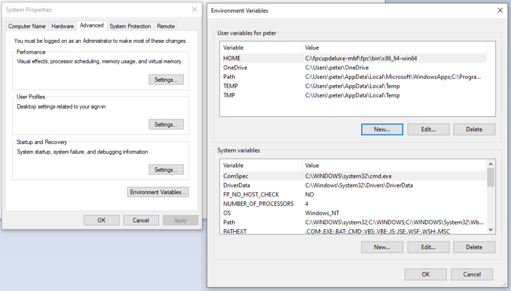
1) Set a HOME environment variable to set a valid path on the PC
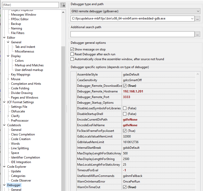
in Lazarus TOOLS//OPTIONS//Debugger ……..
select remote GDB debugging.
change “EncodeCurrentDirPath” and “EncodeExeFileName” to “gdfeNone”.
check the “Debugger_remote_downloadexe” option.
set GDB server IP address=PI address and port=3333.
remove the “.elf” extension from the program file e.g. “Blinky.elf”.
It helps to create a batch file e.g. “final.bat” and add this to the project options to be executed after every build.
del test
ren test.elf test
So that’s it folks. Ensure the GDB server is running on the Pi. Press F9 on Lazarus and the program will download from the PC to the STM32 and start running. You can set up to 6 simultaneous breakpoints. Memory and variables can be viewed (but not updated). F7 and F8 single stepping is also enabled.
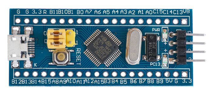
I have recently ventured into the world of 32bit Micro-controllers after spending years with the PIC 8 bit controllers. The card shown above hosts the ST microelectronics STM32 F103 C8 T6. The card costs < £3.50 and is excellent value for money and on par with using an 8 bit PIC.
The chip has 128k of program memory, 20k of RAM and runs at 72MHz. It has on board peripherals e.g. 3 UARTS, 8 channel dual ADC and a USB interface. There is also a connector for on-board debugging (next post).
There are several general purpose IO pins ready to solder. The board is self-contained and powers off 3.3v or 5v supplies.
The board can be programmed using the Arduino tools and there is plenty of C code support. I prefer to use PASCAL for programming and was over-joyed to discover that the Lazarus/Free pascal tools are able to cross-compile and debug code on a Windows PC.
I installed the latest Lazarus and Free Pascal tools for Windows and then added additional software.
Cross compiler for Cortex ARM chips
MBF framework of software to provide interface and kernel for the STM32 chip
There are some example projects for the “Blue-Pill”. The “hello world” equivalent for microcontrollers is called “Blinky”. This program will flash the on-board green LED.
The output of the compilation is a binary file – “Blinky.bin”. This is downloaded to the STM32 card using a serial link from the PC via a FTDI USB card.
Cross-compilation is selected in the Lazarus project options and these are set in the example projects. Note that they need to be set up for new projects and it is best to copy a new project from an existing one to inherit the right settings.
There are many tutorials on how to do this. To summarise:
Connect FTDI USB card to PC. This creates a virtual comm port (e,g, COM3) on the Windows PC. The FTDI converts the asynchronous serial communications to 3.3 volt logic levels. (different to RS232 comms in that the logic is inverted and voltages are different)
Connect wires from the FTDI card to the STM32 GPIO pins A9 and A10. A9 is transmit data and A10 is receive data.
Install a serial bootloader program “STMFlashLoader Demo.exe” from the STMicroelectronics website.
Move the boot 0 jumper from operational to program mode.
Run the bootloader, configure the serial port and speed, open the “Blinky.bin” file and download. The program should start automatically.
This is fine for simple programs, but if you are really serious, FORGET the last instructions and look at the next post. Using an additional Raspberry PI zero card (£10) and some basic soldering, it is possible to do superfast downloads and in circuit debugging from your Windows PC !!
A FTDI USB card is not needed and the PI can also serve as a communications terminal for reading and writing.
I am interested in experimenting with audio digital filters, FFT and wavelet analysis.
An interesting application is the Goertzel algorithm. This does a frequency domain analysis of the audio signal like a FFT but it only analyses a single frequency at a time. This can be faster than a FFT if you know which frequency you are looking for…
e.g. Touch tone, Musical harmonics
There is a setup phase where a coefficient is calculated for a fixed frequency(s).
The analysis process is called with a fixed buffer of “N” samples. It returns the magnitude squared of the required signal ignoring phase.
const
 SAMPLING_RATE    = 8000.0;   //8kHz

var
 coefficient : real;
 sine : real ;
 cosine : real ;
 N : integer; // number of points in an audio chunk

// Call this once, to precompute the coefficient(s)
 procedure InitGoertzel;
 const
  PI = 3.141592653589793;
 var
   TARGET_FREQUENCY : real;
   i : integer;
   k : real;
   floatN : real;
   omega : real;
 begin
     TARGET_FREQUENCY := 1200; // Hz
     floatN :=  N;
     k :=  (floatN * TARGET_FREQUENCY) / SAMPLING_RATE;
     omega := (2.0 * PI * k) / floatN;
     sine := sin(omega);
     cosine := cos(omega);
     coefficient := 2.0 * cosine;
 end;
This is the analysis function
function ProcessSamples ( var buff : TBuff ) : real;
// returns the magnitude SQUARED

 var
    Q0 : real;
    Q1 : real ;
    Q2 : real ;
    i : integer;
 begin
    Q2 := 0;
    Q1 := 0;
    for i := 0 to N - 1 do
    begin
       Q0 := coefficient * Q1 - Q2 +  buff[i];
       Q2 := Q1;
       Q1 := Q0;
    end;
   result := Q1 * Q1 + Q2 * Q2 - Q1 * Q2 * coefficient ;
 end;
This will record a 10 second segment to the file “out.wav”
Another useful tool is called “sox” that allows you to change to different file formats and compressions.
sudo apt-get install sox
I wrote a simple program that listens and starts a new recording if some interesting sound is perceived. This is done by computing the average noise level and triggering if it rises above a fixed threshold. The examples build open the first part.
The sound chunks are then written to a file for a specified duration after the triggering. The data is written in raw format. The sox utility is then invoked to convert the raw file to an “OGG” file….
The file is declared and created as follows:-
var
F : longint;
... ... ... ...

F := FileCreate ('record.raw');
After reading the audio chunk the noise level can be computed as follows:-
var
   accumulator, noiseLevelSqr, threshold : real;
   j : integer;

threshold := 4000.0
rc := snd_pcm_readi(handlePtr, @ buffer[0], frames);
   // check rc for errors as shown before

accumulator := 0.0;
for j := 0 to frames-1 do
begin
     accumulator := accumulator + (buffer[j] * buffer[j]);
end;
noiseLevelSqr := accumulator / frames;

if noiseLevelSqr > (threshold * threshold) then
begin
   // detection triggered
end;
The audio data is written in raw format as follows :-
for i := 1 to 30 * 8000 do //30 seconds @ sample rate of 8k
begin
   rc := snd_pcm_readi(handlePtr, @ buffer[0], frames);
   // check rc for errors as shown before

   FileWrite(F, buffer[0], xsize);
end;

FileClose(F);
The data is then converted to a WAV file (record.wav) as follows:-
I have been recently investigating how to record sound and process it using the Raspberry Pi Zero. I have used the USB connection to an external microphone rather than build an audio interface, The USB microphone pictured above (£1.83 from China!!) works quite well when plugged in, maybe not high fidelity but pretty good for my purposes.
I wanted to program an interface to the microphone using Lazarus and FreePascal, which in my opinion is the best environment for easily developing software on the Pi.
I downloaded a library to interface to ALSA that handles MIDI and Audio. (I used the MIDI parts in an earlier project.) The library is at https://sourceforge.net/projects/fpalsa/ . There are no instructions on how to use it and I ended up creating an intermediate unit to access it. I found some examples in C which I adapted for PASCAL.
The first code example shows how to use the library to record sound.
You firstly open up a connection in a similar way for a file.
implementation
 uses unitAlsaInterface, crt;
 var
   params: array [0..999] of byte;

 procedure test;
 var
   rc: cint;
   handlePtr: Psnd_pcm_t;
   handle: snd_pcm_t;
   frames: snd_pcm_uframes_t;
   val: cuint;
   dir: cint;
   buffer: array of smallint;
   xsize: integer;
   i: integer;
   running : boolean;

 begin
   writeln();
   writeln('Audio Test');
   handlePtr := @handle;

 // Open PCM device for recording
   rc := snd_pcm_open(@handlePtr, 'default', SND_PCM_STREAM_CAPTURE, 0);
   if (rc < 0) then
   begin
     writeln('unable to open pcm device', snd_strerror(rc));
     exit;
   end;
You then set up the configuration parameters. Here you specify if the sound is stereo or mono, the desired sample rate, the desired data format and the size of a chunk of audio to be read at a time.
// Allocate a hardware parameters object.
// Hack! just assign a big array instead of allocating memory
// Fill it in with default values.
   rc := snd_pcm_hw_params_any(handlePtr, @params);

 // Interleaved mode
   snd_pcm_hw_params_set_access(handlePtr, @params, SND_PCM_ACCESS_RW_NONINTERLEAVED);

 // Signed 16-bit little-endian format
   snd_pcm_hw_params_set_format(handlePtr, @params, SND_PCM_FORMAT_S16_LE);

 // MONO
   snd_pcm_hw_params_set_channels(handlePtr, @params, 1);

 // 8k bits/second sampling rate
   val := 8000;
   snd_pcm_hw_params_set_rate_near(handlePtr, @params, @val, @dir);

 // Set period size to 32 frames.
   frames := 32;
   snd_pcm_hw_params_set_period_size_near(handlePtr, @params, @frames, @dir);

 // Write the parameters to the driver
   rc := snd_pcm_hw_params(handlePtr, @params);
   if (rc < 0) then
   begin
     writeln('unable to set hw parameters', snd_strerror(rc));
     exit;
   end;

 // Use a buffer large enough to hold one chunk
 // Note the earlier request to set frame size maybe be overrided and adjusted.
   snd_pcm_hw_params_get_period_size(@params, @frames, @dir);

// Get the chunk size and allocate memory to buffer it
// Buffer is an array of 16bit signed integers
   xsize := frames * 1; //* 2 bytes/sample, 1 mono channel
   setLength(buffer, xsize);
You then continuously read standard chunks of audio until when you want to finish. ALSA buffers up the audio.
running := true;
while running do
begin
 rc := snd_pcm_readi(handlePtr, @buffer[0], frames);

if (rc = -32) then
begin   // EPIPE means overrun
  writeln('overrun occurred');
   snd_pcm_prepare(handlePtr);
end
else
if (rc < 0) then
begin
  writeln('error from read:', snd_strerror(rc));
end
else
if (rc <> frames) then
begin
   writeln('short read', rc);
end;

// analyse sound recorded buffer
for i := 0 to frames - 1 do
begin
  // buffer[i]
end;


... etc ... etc ... etc ...